-
Resistors
- VR1 (47 Kilo ohms Variable resistance)
-
Transistors
- T1 (BC108)
-
Miscellaneous
- Battery 9V DC
- LDR
- Relay (6V /300 Ohms)
- Bulb (230V /60W)
- PCB or Breadboard
- Flexible Wire
- Soldering rod etc..
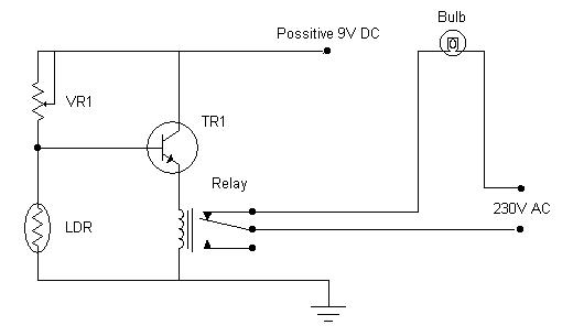
The circuit above shows a simple application of light operated switch. This circuit senses the ambience light and depending on the presence/absense of sufficient ambience light, it turnes the bulb On/Off automatically. The bulb gets on when there is insufficient ambience light (e.g evening or night time) and switches off automatically when enough ambience light is present. (e.g In day time, when the sun light is present additional light may not be needed.) This bulb can also be your street lamp that needs to be switched on every evening, and switched off every morning. The circuit does this job automatically without any manual interference.
Lets See how this works :- During day time when sunlight falls on LDR, the resistance of LDR decreases. The decrement of resistance causes more potential across VR1 and very less potential across LDR. The potential across LDR is directly fed to the base of transistor TR1 (shown in circuit). Because of the low potential difference across TR1's base and emitter, the transistor TR1 goes into cutoff, and restricts any flow of current from collector to emitter. This non availability of sufficient current causes the relay to get de-magnetized and switches off any device attached to it (bulb in this case). Similarly when sunlight is not present (i.e. at night), the resistance of LDR increases and hence the potential across LDR also increases. The increased potential causes transistor to move from cutoff to saturation, allowing maximum current to pass from collector to emitter. The increased current turns the relay ON and also the bulb attached to it.