Since, we are done with the design part in our last topic now its time for coding. For this, first we should understand the structure in which this coding should be done. To represent any design properly, we need to understand two types of coding structure, ARCHITECTURAL and BEHAVIORAL.
BEHAVIORAL coding is done for modules, where logic inside the entity (module/block) has to be coded. ARCHITECTURAL coding is required for integration, where various modules are instantiated and connected with each other.
Lets take an case study and understand whole design process from scratch..
In this case study we will do following..
- Taking design specification
- Designing architecture
- Dividing design into sub-modules
- Coding individual modules (entities)
- Integrating these modules (architectural coding)
Below is the design specification of a sample design Byte Counter, this design takes serial bit data in, converts bits to byte and gives out 64th, 128th and 256th byte out.
Lets go through the detailed specifications first.
Design specification : The design specification says following things..
- We need to design a chip that counts number of bytes.
- This chips get serial bit data input with one bit per clock.
- All clocks will not contain valid data, hence input bit will be valid only when bit_valid= '1'.
- The chip should generate 4 outputs; 64_byte_rec, 128_byte_rec, 256_byte_rec and byte_out.
- 64_byte_rec pulse signal will indicate that chip has received 64 bytes, this pulse will remain high for only one clock. 128_byte_rec and 256_byte_rec shall also follow same fashion and generate pulse on reception of 128 and 256 bytes respectively.
- "byte_out" is output byte, all 64th , 128th and 256th bytes will be given out by this chip.
- Internal logic may work on positive edge or negative edge but the outputs should be asserted along with the +ve edge of the clock.
- 'reset' is active low, means chip will be under reset when reset = '0', under reset chip will ignore all inputs and won't generate any output. Chip will start functioning as soon as 'reset' is '1'.
- 'clock' is a 10MHz with 50% duty cycle
Architecture : Now, we are very much clear about the specifications, lets divide our design into sub modules and finalize functionality of each module. Here I would like to break the whole design into two sub modules, byte converter and byte counter . The block diagram below shows chip and sub-module's interface. Lets discuss functionality of each module.
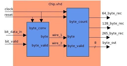
| Byte Converter : |
This module byte_conv will take bit_data_in and bit_valid as inputs, and will convert bits into byte. Once this module is ready with byte, it will indicate with byte and byte_valid indications. byte_valid is a pulse signal and will remain high only for one clock. |
| Byte Counter : |
byte_counter receives bytes from byte converter and keeps counting number of bytes received. As the number of bytes received are 64 or 128 or 256 this module generates 64_byte_rec , 128_byte_rec and 256_byte_rec pulses respectively. Along with these pulses corresponding byte is also given out on byte_out. |
We will code the above design in three files,
-
chip.vhd
- This is a architecture file for chip entity.
- Architecture file only contains instantiation of modules the and connection between them.
- This file will not contain any logic component, only the connections between sub-modules.
- This file will be provide interface to submodules, and convey output on submodules out of chip. Make sure that this file is 100% as per required specification.
-
byte_conv.vhd
- This is a behavioral entity for byte_conv module.
- This will contain actual code responsible for byte_conv's behavioral.
- This contains actual hardware logic for generation of signals to other blocks.
- This file won't contain any other behavioral or architectural entity within it.
-
byte_count.vhd
- This is also a behavioral entity for byte_count entity/module.
- This will contain actual code responsible for byte_count's behavioral.
- This contains actual hardware logic for generation of signals to other blocks.
- This file won't contain any other behavioral or architectural entity within it.
Now, since byte_conv.vhd and byte_count.vhd are behavioral entities, we will code them in behavioral style. Chip.vhd is the only architecture entity and we will code it in struct or arch style. In next topic we will see what is behavioral and structural coding.